Aim :
3D meshing in Hyperworks.
Objective :
To carry out the 3D meshing in hyperworks following the given quality criteria.
Model 1- Housing model
Create the tetra mesh
Elements sizes: Min- 2mm, Target- 5mm,Max- 7mm
Tet collapse: 0.15
Model 2 and 3 - create the 3D mesh with 6mm
Introduction :-
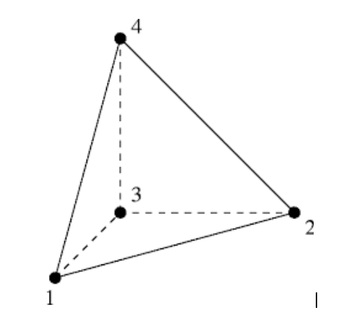
Tetrahedral is a four noded solid element which can be generated through tria elements by creating a volume and also through the existing volume of the geometry.
There are two methods of tetra meshing.
1) Automatic mesh:
This approach is limited to simple geometries and the prerequisite is an error free CAD model. The user just has to select the volume and the software automatically carries out the meshing as per the speci"ed element length, quality criteria, etc.
Advantage: Very quick, no meshing e!orts
Disadvantage: Results in a very high number of nodes and elements. There is no control over the mesh flow and the speci"c mesh pattern requirement (like bolted, welded joints or contact surface simulation).
2) 2-D (Tria) to 3-D (Tetra):
This is the most commonly used method. Quad or tria meshing is carried out on all the outer surfaces of the geometry. During the tetra meshing the quads are automatically split into trias which then serve as the “basis” of the tetra elements.
Procedure :
Method 1: 2D to 3D tria
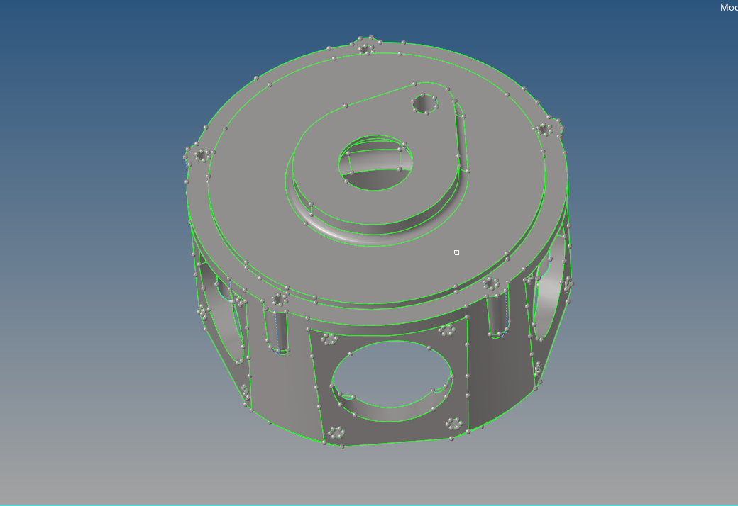
Step 1 : Opening the file and performing the geometry clean up
The housing model here is going to be meshed by using the 2D to 3D tria method so it is cleaned in the primary stage to avoid the element failure.
_1603784065.png)
Fig- housing model (surface model)
Clean up :
The surface is cleaned in the region to remove the any two lines that is having the distance less than 2mm(2 is the minimum size of the element )
For cleaning up we are using the quick edit tool
Points >replace
_1603784174.png)
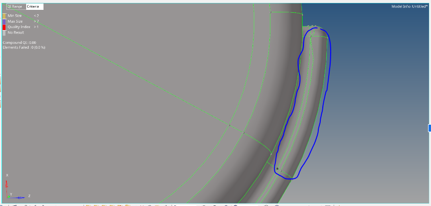
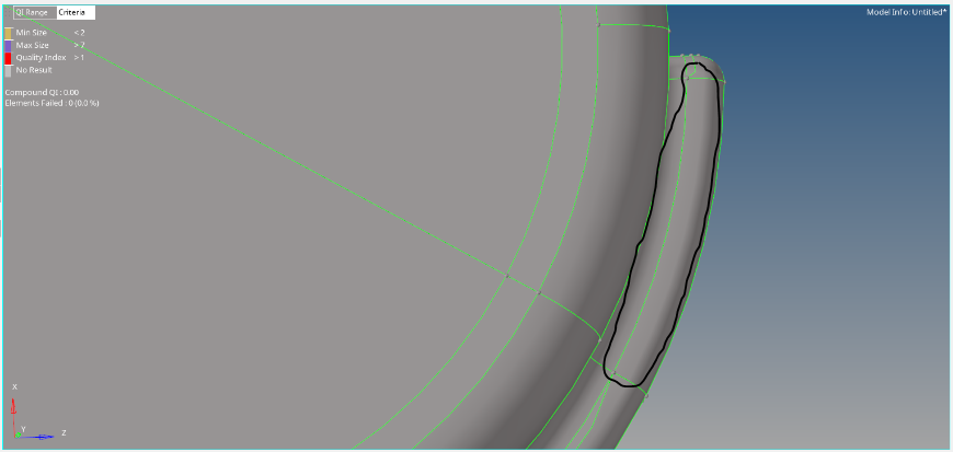
Fig-Lines were patched using replace points
Step 2 : Performing the 2d shell mesh :
Now the 2D meshing is performed using the only tria elements and all the shell kept under the mentioned quality criteria.
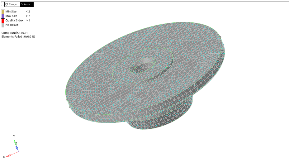
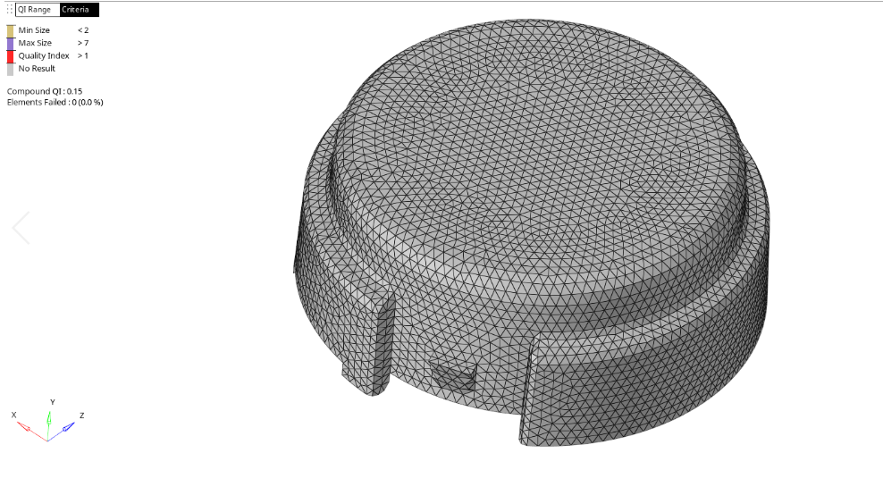
Fig- housing model shell meshed with no failed elemnts
Step3 : 2d to 3d tria conversion
After the shell mesh is performed they need to be converted into solid tria elements. So select 3D> tetramesh option
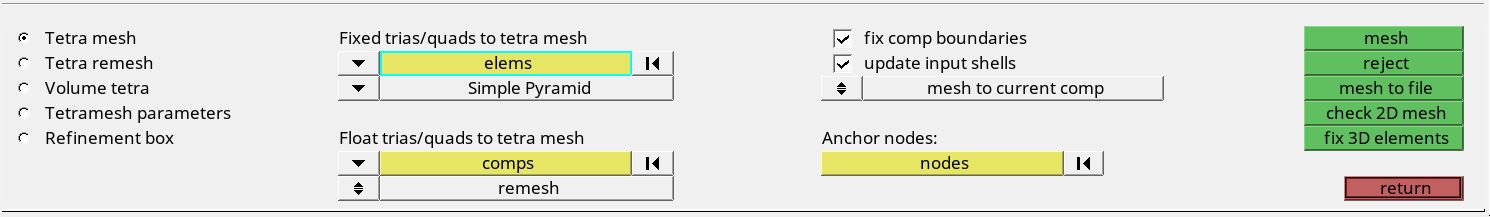
Then select the elements under the fixed tria/quad to tetra option and then do the mesh
Fixed tria to tetra option ensures the connectivity of the tria with the tetra.
Use the mask option to see the if the volume mesh is performed correctly
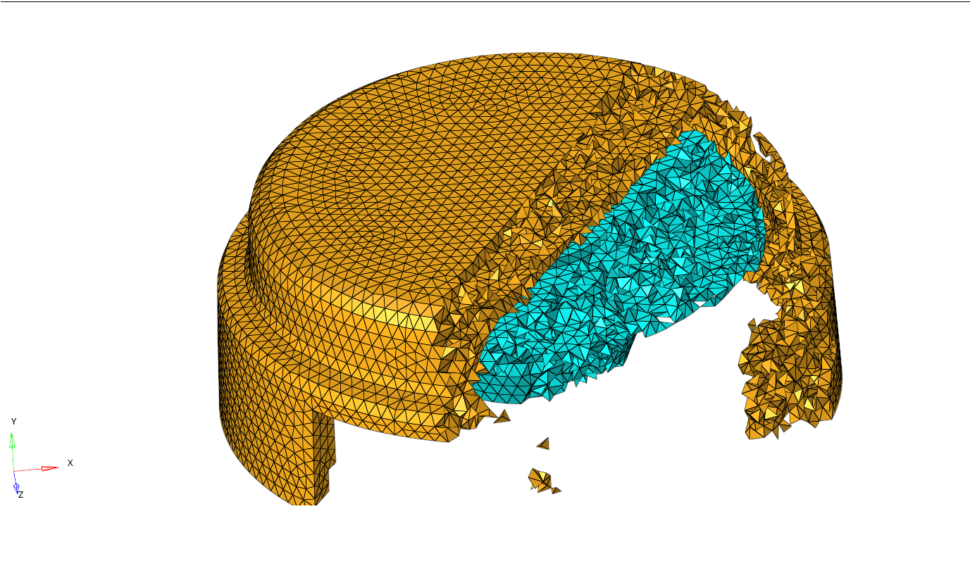
Fig- Tetra meshing for housing model
Method 2 : Automatic solid meshing
A- Using the utility option
This is one of the approaches to perform the automatic 3D meshing. The steps to perform are as follows
2.There is no need to delete the solids since this is only the surface geometry.
3.The click on the view > browsers> hypermesh> utility( we can see the utility tab in the tab bar)
_1603787106.png)
4.Select the geom/mesh from the utility menu and then select the quick mesh.
5.A new sub panel opens for the quick mesh to input the parameters.
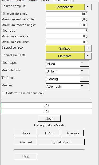
6.The new tetra mesh model is saved under the name quick test.
_1603787258.png)
Fig- Model2 tetra mesh using utility option
B- Using the volume tetra :
This method is one of the quickest methods to perform the tetra meshing. The steps to perform the volume tetra are as followed.
The component here is the suspension assembly and we will be working on one side of the assembly since both the sides are the same. Also there are a number of components so we will be working part by part.
_1603789360.png)
Fig- Chassis model for volume tetra
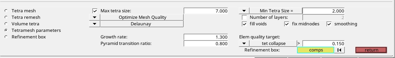
2.The volume tetra requires only the solid model so no need to delete the solid here. Go to 3D> volume tetra
3.The volume tetra has the same parameters that needs to be feeded
(These two option are used to refine the mesh in the region of curves or converging parts so that there is smooth transition of the elements.)
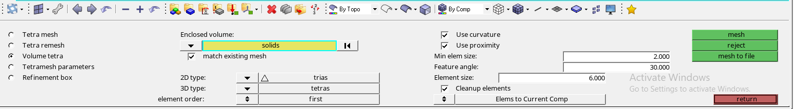
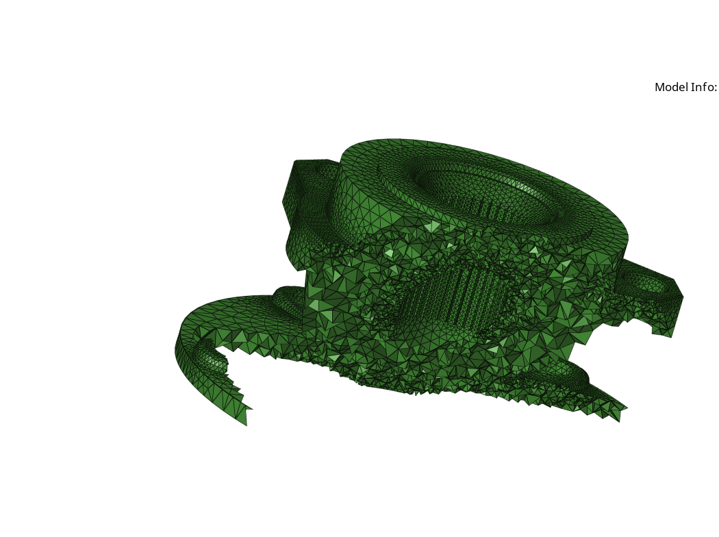
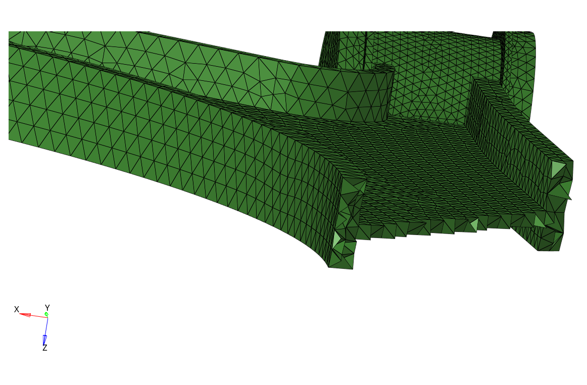
Fig- Chassis component tetra mesh sesction view
Tet collapse
Tet collapse is an important criteria dealing with the volumetric mesh also it is only applicable to the tetra elements only. As we know that tetra element is 4 noded element having 4 sides and 4 nodes.
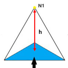
Tet collapse or TET element is the minimum of (h/√A)÷1.24
Where h is the perpendicular distance from node to the opposite face of the TET and
A is the area of the opposite face
fig
Then if the height of the any tetra element falls below the desired height, it will eventually fail for the Tet collapse
There are 2 methods to solve the TET collapse as studied in the article
This option is a manual method used to solve the tet collapse. Step to perform are as follows
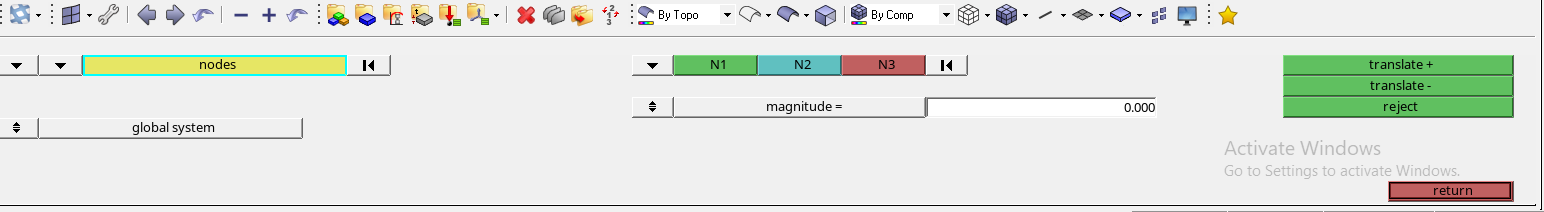
Fig- translating the element
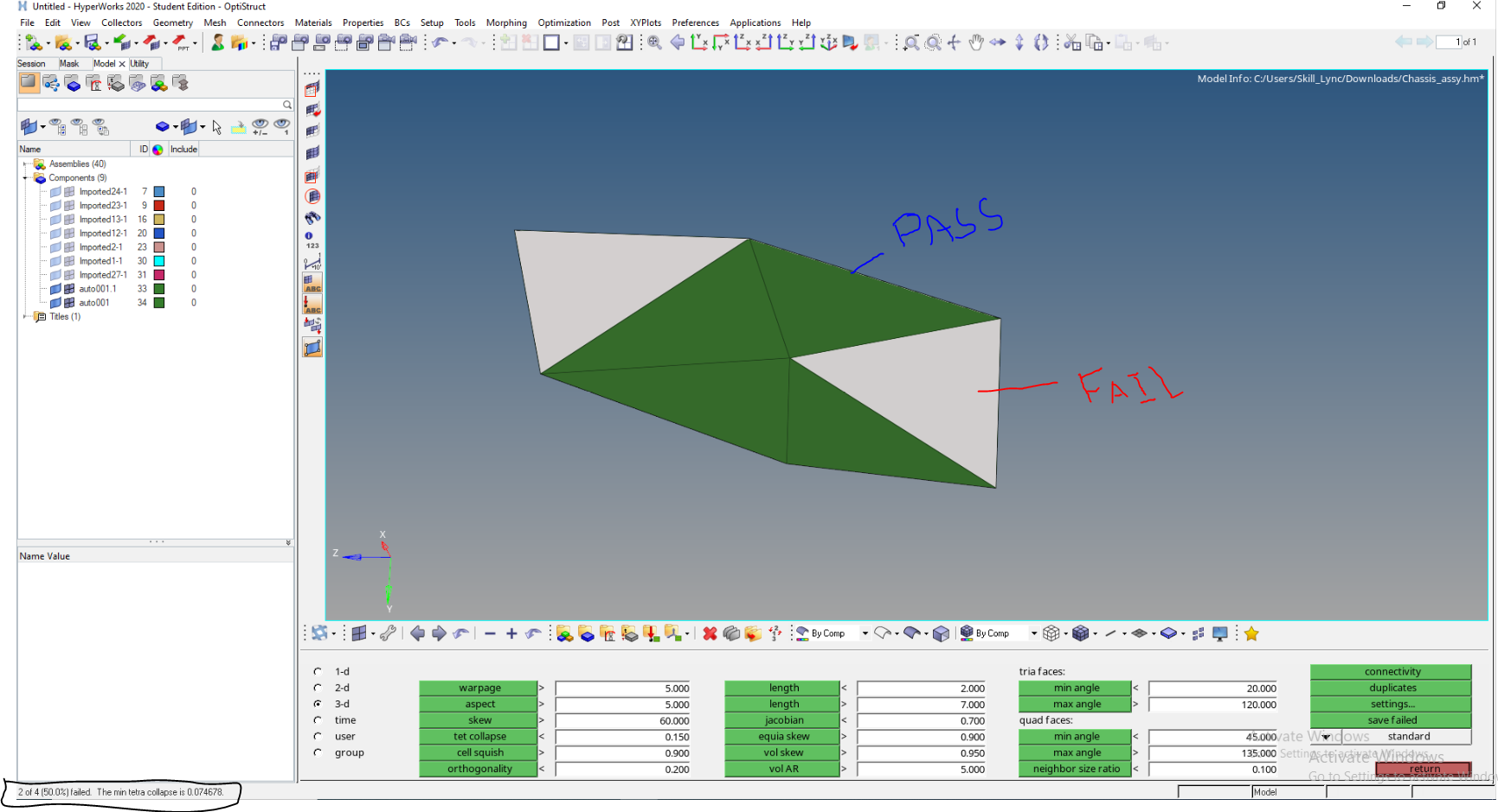
2.Using the tetra remesh
This automatic method to solve the tet collapse at once. Step are as followed
Results :
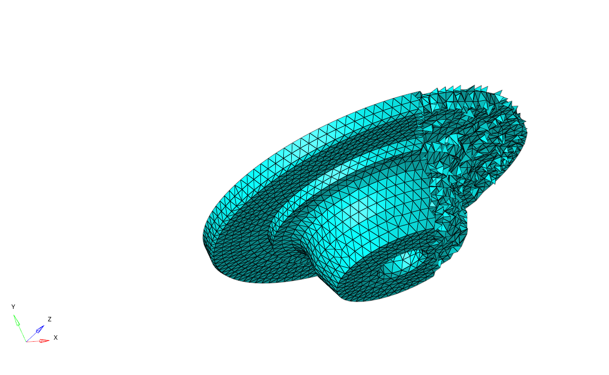
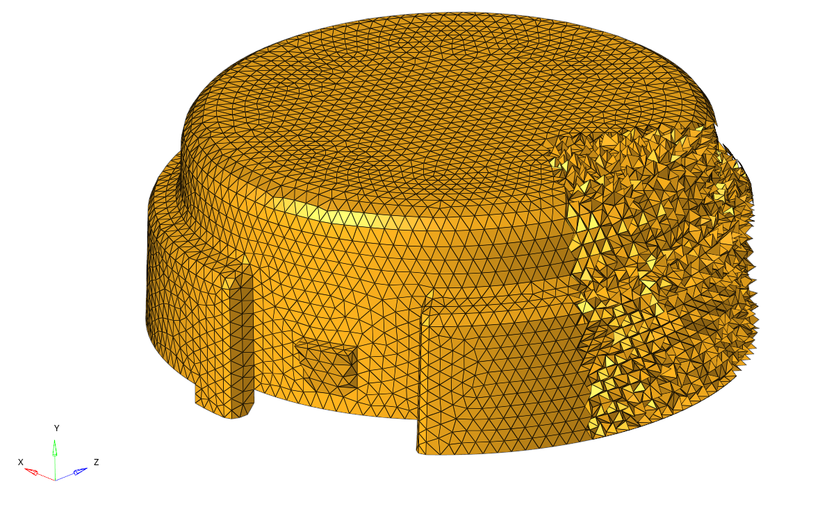
Fig- housing model
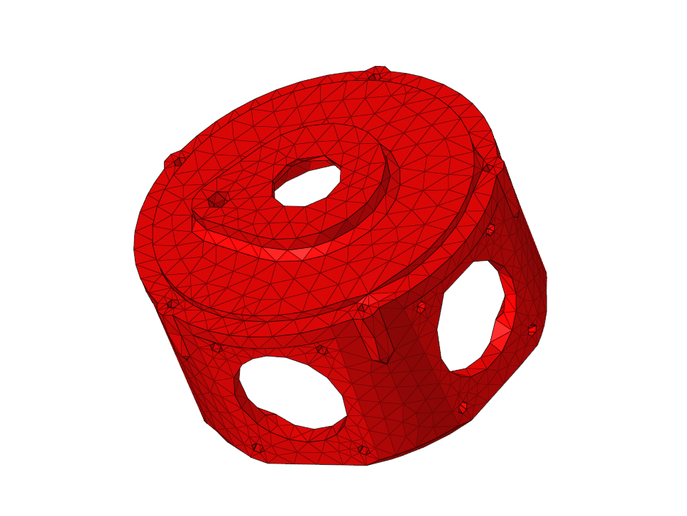
Fig - model using utility tetra mesh
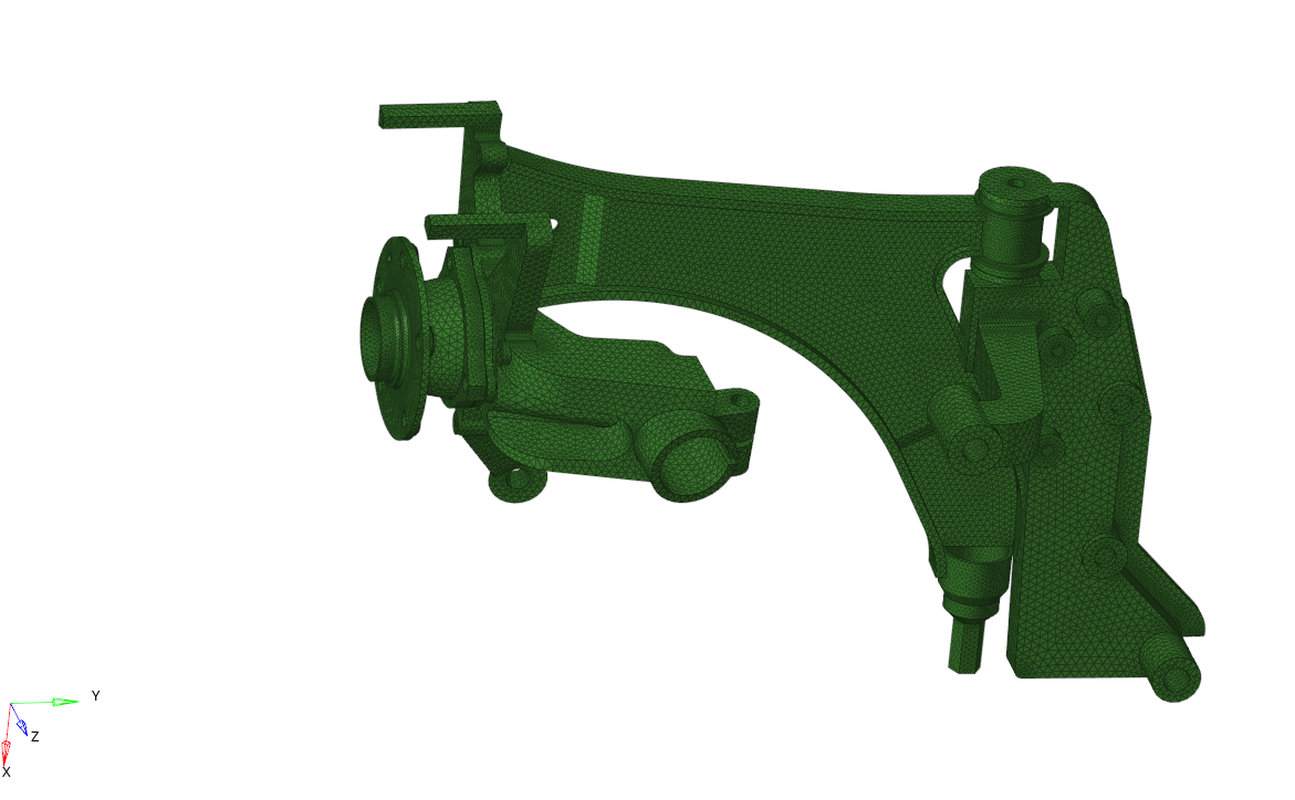
Fig- chassis model volume tetra
Conclusions :
All the model were meshed in 3D using the 2D to 3D , utility and volume tetra mesh respectively along with solving the tet collapse and kinks . The meshed obtained in the utility were not so good as compared to other two. Also the number of elemnts and the tet collapse were more in the volume tetra mesh method.
Link for the model :https://drive.google.com/drive/folders/1JbnjuM2KD6BwxN1_292qCKjRywDVOU8L?usp=sharing
Refrences :https://skill-lync.com/knowledgebase/understanding-tetra-meshing-and-tet-collapse